Capabilities on Augusta Aircraft

TGH Aviation offers aircraft component repair on the following Augusta Models. Below is a list of the most commonly requested repairs and does not eliminate capabilities on other instruments used in this make of aircraft. If you need an instrument repaired that is not listed below, please call our Sales Department at 1 (800) 843-4976.

Augusta


Capabilities on Airbus Aircraft

TGH Aviation offers aircraft component repair on the following Convair Models. Below is a list of the most commonly requested repairs and does not eliminate capabilities on other instruments used in this make of aircraft. If you need an instrument repaired that is not listed below, please call our Sales Department at 1 (800) 843-4976.

Airbus


Capabilities on Challenger Aircraft

TGH Aviation offers aircraft component repair on the following Challenger Models. Below is a list of the most commonly requested repairs and does not eliminate capabilities on other instruments used in this make of aircraft. If you need an instrument repaired that is not listed below, please call our Sales Department at 1 (800) 843-4976.

Challenger Capabilities

TGH Aviation Celebrates 60 Year Anniversary

TGH Aviation Celebrates 60 Year Anniversary

Auburn, CA, March 30th, 2017

TGH Aviation, one of the most trusted and respected Part 145 Repair Stations in the industry, this year celebrates its 60th anniversary. TGH Aviation takes pride in its humble beginnings and appreciates the loyalty and dedication of both customers and employees throughout the past six decades. The company will commemorate the occasion with a number of customer appreciation specials and anniversary promotions throughout the year.

In 1957 founder Emery “Claude” Oxley Senior set out with a vision to specialize in the repair of gyroscopes for General Aviation aircraft. Claude originally began working out of his home in Riverside, California before his son Emery moved the business to a small wooden building in Auburn, California and joined forces with Chief Engineer, Rich Anderson. The early years were critical to the long term success of The Gyro House, now known as TGH Aviation. The founders built a strong infrastructure for the future by developing the TGH Aviation reputation as a top quality aircraft instrument repair facility with superior customer service.

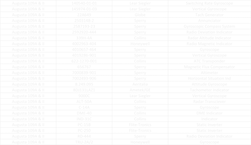
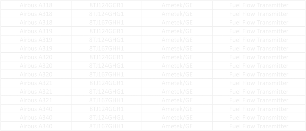
Over the course of the last 60 years, TGH Aviation has vastly expanded its capabilities beyond gyroscopes, evolving into a diverse aircraft instrument repair facility that has become known world-wide. TGH Aviation now offers over 20,000 service capabilities, including the repair of primary flight instruments, avionics, aural warning systems, fuel flow transmitters, and their related indicators and refueling sensors. Today TGH Aviation is a valued supplier to the United States Department of Defense, NATO and a world-wide network of aviation maintenance facilities and parts brokers while still maintaining its legacy customer base of General Aviation pilots.

TGH Aviation provides outright sales, exchange sales, avionic installations and upgrades, repair services, and holds distributorships for most of the major manufacturers of the aforementioned product lines. The company’s repair shop customer base spans all areas of the industry from general aviation, corporate aviation and commercial aviation. The customer base includes airlines, parts brokers and maintenance facilities on five continents.

The past 60 years have been a hugely successful time for TGH Aviation, which now consists of a fully operational repair station, fuel lab, online pilot supply store and an avionics hangar. A veteran-owned company, TGH Aviation employs forward-thinking, growth-oriented management and all employees work to build the company reputation while improving industry presence and stature. The company is delighted to have become a part of the local community and to have had the pleasure of working with and meeting many people over the years and look forward to continuing to build on these strong relationships in the future.

As TGH Aviation looks to the next 60 years the mission continues to be to provide customers with high quality products, overhauls and repairs, all delivered with premiere customer service. As one of the most trusted and respected Part 145 Repair Stations in the industry today, TGH Aviation strives to create a great customer experience each and every time.

For a complete list of capabilities, go to www.tghaviation.com for more information.

Pitot Static System…Airspeed Calculation

Pitot Static System…Airspeed Calculation


A.  Airspeed Calculation:

Airspeed is calculated as a function of the difference between Pitot Pressure and Static Pressure as follows:

Calculated or Indicated airspeed is indicated airspeed corrected for instrument errors, position error (due to incorrect pressure at the static port) and installation errors.

Calibrated airspeed values less than the speed of sound at standard sea level (661.4788 knots) are calculated as follows:


pitot picture.jpegminus position and installation error correction.


Where


Vc
 is the calibrated airspeed,


qcis the impact pressure (inches Hg) sensed by the pitot tube,


P0is 29.92126 inches Hg; static air pressure at standard sea level,


a0is 661.4788 knots:, speed of sound at standard sea level


Units other than knots and inches of mercury can be used, if used consistently.

This expression is based on the form of Bernoulli’s equation applicable to a perfect, incompressible gas. The values forP0and   A0_smallare consistent with the ISA i.e. the conditions under which airspeed indicators are calibrated.

Keep in mind that this is for your basic vanilla airspeed indicator and does not include calculations for TRUE Airspeed for which you must include the variables of True Temperature and True Altitude.


Stay tuned for upcoming Blogs

Pitot Static System…. Inside & Out

Pitot Static System ….Inside & Out


A. Pitot Pressure:
Pronounced: PEE-TOE, it is a French word

Pitot pressure is the measurement of the air forced into the Pitot Tube by the movement of the aircraft through the air. Pitot tubes are mounted on the aircraft facing forward so that air is forced into them. Most small aircraft have only one tube, larger aircraft have a redundant system and will have two tubes. The most common manufacturer of these tubes is Rosemont Corp. which is a division of BF Goodrich. Also on larger aircraft, those that fly at higher altitudes, the Pitot Tube is heated in order to prevent icing, smaller aircraft typically do not have this function.

The Pitot Tube is connected directly to the back of the airspeed indicator (the Pitot input) and if the aircraft is so equipped also to the Air Data Computer via a hose which is typically either plastic or rubber


B. Static Pressure:

Static pressure is the measurement of the ambient barometric pressure at the aircraft’s CURRENT location AND CURRENT Altitude.
The Static Port is located in a position on the aircraft that will not be affected by air flow as the aircraft moves through the air. This is typically on the side of the fuselage but can also be on the back side of the Pitot Tube or any other number of locations, it varies by the aircraft. Again smaller aircraft will typically have one Static Port, larger aircraft with redundant systems will have two.

The Static Port is connected directly to the following equipment, depending on aircraft configuration: The Airspeed Indicator (Static Input), the Altimeter, the Vertical Speed Indicator, the Altitude Encoder, the Air Data Computer. Again connection is typically made via a hose either rubber or plastic.


C.  Airspeed Calculation:

Airspeed is calculated as a function of the difference between Pitot Pressure and Static Pressure as follows:


Calculated or Indicated airspeed is indicated airspeed corrected for instrument errors, position error (due to incorrect pressure at the static port) and installation errors.

Calibrated airspeed values less than the speed of sound at standard sea level (661.4788 knots) are calculated as follows:

pitot picture.jpeg
minus position and installation error correction.


Stay tuned for upcoming Blogs

Frequently Asked Altimeter Questions

Frequently Asked Altimeter Questions


The pointers on my altimeter are very jumpy and stick sometimes.
What is wrong?

The altimeter is exposed to the outside atmosphere. This includes all of the dirt and dust present in that atmosphere. Dirt and dust will get into the gears and cause them to stick and bind, the vibration from the aircraft will help the gears to overcome this problem but they will be very jumpy and become worse as the unit gets older. This unit needs an overhaul.


Can I convert my milli-bar altimeter to InHg or vice versa?

Yes, altimeter dials can be converted, provided that the manufacturer has published a procedure for doing so. If there are no published, FAA Approved, procedures then, no, this modification cannot be accomplished.


How often does my altimeter need to be calibrated?

The FAA requires that the aircraft static system be tested and certified biannually. The altimeter is a part of that system.


The altimeter ID plate says that it is a 35,000 Ft. altimeter, but the repair shop that overhauled my altimeter marked the unit as being certified to 30,000 Ft. Why the difference?

As altimeters get older and the parts wear the unit will become inaccurate at the higher end of its range. This does not mean that the altimeter can no longer be used; it just has to be used at the lower altitude. Therefore, it will be sold only to customers who request a lower altitude unit, typically general aviation.


What is a “car” altimeter?

Sometimes, if a unit is so old and worn that it can no longer be used in an aircraft then these units are sold at a discounted price for use in other than aircraft, typically people will use them in motor homes, cars, and boats.


Along with my altimeter, I received a correction card. What is that?

Altitude is a non-linear function.  It is impossible to calibrate an altimeter to be absolutely accurate at all altitudes. Therefore, a certain amount of error is allowable. The correction card advises the users of the amount of error in a particular altimeter. As each altimeter will have its own characteristics, the error card is identified with the unit’s serial number.


What is a TSO?

TSO stands for Technical Standard Order. This is an FAA document, which defines how a specific type of instrument should work in order to be considered airworthy. Altimeters manufactured by the following companies typically are manufactured to TSO standards: United Instruments, Kollsman, Garwin, and Aerosonic. Altimeters manufactured by the following companies typically are not qualified to TSO specifications:UMA & Falcon. If an instrument is certified to a TSO, it must state such on the ID plate. If it does not state the TSO on the nameplate then you must assume that it is not qualified to the TSO.


What are the typical failure modes of an altimeter?

  1. Sticky/jumpy pointers
  2. Inability to properly adjust the Kollsman window
  3. Out of calibration
  4. Worn pivots and/or jewels
  5. “Oil-canning” of the aneroid


How to Read a 3 Pointer Altimeter

How to Read a 3 Pointer Altimeter

A three-pointer altimeter, as its name implies, has three different pointers on the front dial. They are the 100-foot pointer, the 1000-foot pointer, and the 10,000-foot pointer. The medium length pointer is the 100-foot pointer, the shortest pointer is the 1000-foot pointer, and the longest pointer is the 10,000-foot pointer. The altimeter dial has 10 major indices numbered 0 through 9. In between each major indice are 4 minor indices. The value of these indices is dependent on the pointer being read. When reading the 100-foot pointer each minor indice equals 20 feet, each major indice equals 100 feet. When reading the 1000-foot pointer each minor indice is equal to 200 feet, each major indice is equal to 1000 feet. When reading the 10,000-foot pointer each minor indice is equal to 2000 feet, each major indice is equal to 10,000 feet. The altimeter in figure 1 is indicating 11,520 feet and is read as follows:


The 10,000 foot pointer is past the 1 and not yet up to the

2 and so it is read as:                                                           1 x 10,000 = 10,000 +

The 1,000 foot pointer is past the 1 and not yet up to the

2 and so it is read as:                                                           1 x 1,000 = 1,000 +

The 100-foot pointer is 1 minor indice past the 5 and so

Therefore, it is read as:                                                        5.2 x 100 = 520

The indicated altitude is the sum of the pointers:                        11,520

barber_pole

Figure 1: Three-Pointer Altimeter

Getting to know your Kollsman Window and Barber Pole

Getting to know your Kollsman Window and Barber Pole


 Reading the Kollsman Window ( Barometric Reading)

The Kollsman window is located at the 3 o’clock position on the altimeter dial. This window allows access to read a sub-dial, which contains the barometric readings. The arrowhead indice located precisely at the 3 o’clock position on the altimeter’s main dial is used as the reference point for reading the barometric sub-dial. Most altimeters will have a sub-dial, which covers the readings from 28.1 InHg (inches of mercury) to 31.0 InHg. On the sub-dial each major indice is read as 0.1 InHg, each minor indice is read as 0.02 InHg.

The Altimeter in Figure 1 reads 29.92 InHg


As previously, stated, weather conditions will greatly affect the pressure of the atmosphere (the barometric reading). Altimeters report altitude as a function of atmospheric pressure. Typically pilots will obtain a local barometric reading from the nearest airport. They will then set the Kollsman window to the setting that they received. This action will adjust the altimeter reading, eliminating error due to local weather conditions.

Some altimeters will have a Kollsman Window, which reads out in milli-bars in lieu of InHg. These are usually altimeters designated for use in Europe. However use of milli-bars has become more common in the U.S. during the last few years. Milli-Bars is just another unit of measurement, 1013.2 milli-bars = 29.92 InHg.


The Barber Pole

The “Barber Pole” on the face of the altimeter is visible only when the altitude is above sea level. When the altitude is below sea level the barber pole is no longer visible. This is provided to avoid the error of reading –1,000 Ft. as being +10,000 Ft.

barber_pole

All About Altimeters

All About Altimeters


General Information

The altimeter provides the basic function of indicating to the pilot the altitude of the aircraft above mean (average) sea level (MSL).  The indicator is normally a 31/8” size dial face with multiple pointers or a combination of pointers and counter drum. Location of this indicator is typically in the top row of instruments near the center of the instrument panel. In a standard “T” configuration panel the altimeter is just to the right of the attitude gyroscope.


Types of Altimeters

The various types of altimeters include:

  1. Three pointer altimeter
  2. Counter Drum Altimeter
  3. Encoding Altimeter

Typical altimeter ranges are:

  1. –1000 Ft. to +20,000 Ft.
  2. –1000 Ft. to +35,000 Ft.
  3. –1000 Ft. to +50,000 Ft.
  4. –1000 Ft. to +80,000 Ft.


Most general aviation altimeters will fall into the first two ranges. Ranges above 35,000 Ft. are typically corporate jets, commercial aircraft, and military aircraft.


Three Pointer Altimeter

The three-pointer altimeter is the most common type of instrument used in general aviation. It is named as such because it utilizes three pointers in order to display the current altitude. One pointer is used to display 100 Ft. increments. A second pointer is used to display 1000 Ft. increments and the third pointer displays 10,000 Ft. increments. The Technical Information Section of this document provides instructions on how to properly read a three-pointer altimeter.


Counter Drum Altimeter

The counter-drum altimeter is named as such because it displays altitude utilizing a single pointer and a rotating drum that displays digits. The drum displays ten thousand and one thousand foot increments. The pointer displays from 0 to 999 feet.


Encoding Altimeter

An encoding altimeter can be of either the three-pointer or counter drum type of altimeter with an encoding module built into it. The encoding module takes the altitude information and converts that data into a digital code. This code is then sent via a set of wires to the aircraft transponder. A transponder is a radio device that reports the aircraft altitude to ground control radar.


Blind Encoder

The blind encoder is a very special type of altimeter. This unit has no dial or read out that is visible to the user. It has only an electronic output to the aircraft transponder. The use of a standard altimeter in conjunction with a blind encoder is often more economical than purchasing an encoding altimeter.


Photo Lineup