TGH Aviation Celebrates 60 Year Anniversary

TGH Aviation Celebrates 60 Year Anniversary

Auburn, CA, March 30th, 2017

TGH Aviation, one of the most trusted and respected Part 145 Repair Stations in the industry, this year celebrates its 60th anniversary. TGH Aviation takes pride in its humble beginnings and appreciates the loyalty and dedication of both customers and employees throughout the past six decades. The company will commemorate the occasion with a number of customer appreciation specials and anniversary promotions throughout the year.

In 1957 founder Emery “Claude” Oxley Senior set out with a vision to specialize in the repair of gyroscopes for General Aviation aircraft. Claude originally began working out of his home in Riverside, California before his son Emery moved the business to a small wooden building in Auburn, California and joined forces with Chief Engineer, Rich Anderson. The early years were critical to the long term success of The Gyro House, now known as TGH Aviation. The founders built a strong infrastructure for the future by developing the TGH Aviation reputation as a top quality aircraft instrument repair facility with superior customer service.

Over the course of the last 60 years, TGH Aviation has vastly expanded its capabilities beyond gyroscopes, evolving into a diverse aircraft instrument repair facility that has become known world-wide. TGH Aviation now offers over 20,000 service capabilities, including the repair of primary flight instruments, avionics, aural warning systems, fuel flow transmitters, and their related indicators and refueling sensors. Today TGH Aviation is a valued supplier to the United States Department of Defense, NATO and a world-wide network of aviation maintenance facilities and parts brokers while still maintaining its legacy customer base of General Aviation pilots.

TGH Aviation provides outright sales, exchange sales, avionic installations and upgrades, repair services, and holds distributorships for most of the major manufacturers of the aforementioned product lines. The company’s repair shop customer base spans all areas of the industry from general aviation, corporate aviation and commercial aviation. The customer base includes airlines, parts brokers and maintenance facilities on five continents.

The past 60 years have been a hugely successful time for TGH Aviation, which now consists of a fully operational repair station, fuel lab, online pilot supply store and an avionics hangar. A veteran-owned company, TGH Aviation employs forward-thinking, growth-oriented management and all employees work to build the company reputation while improving industry presence and stature. The company is delighted to have become a part of the local community and to have had the pleasure of working with and meeting many people over the years and look forward to continuing to build on these strong relationships in the future.

As TGH Aviation looks to the next 60 years the mission continues to be to provide customers with high quality products, overhauls and repairs, all delivered with premiere customer service. As one of the most trusted and respected Part 145 Repair Stations in the industry today, TGH Aviation strives to create a great customer experience each and every time.

For a complete list of capabilities, go to www.tghaviation.com for more information.

Pitot Static System…Airspeed Calculation

Pitot Static System…Airspeed Calculation


A.  Airspeed Calculation:

Airspeed is calculated as a function of the difference between Pitot Pressure and Static Pressure as follows:

Calculated or Indicated airspeed is indicated airspeed corrected for instrument errors, position error (due to incorrect pressure at the static port) and installation errors.

Calibrated airspeed values less than the speed of sound at standard sea level (661.4788 knots) are calculated as follows:


pitot picture.jpegminus position and installation error correction.


Where


Vc
 is the calibrated airspeed,


qcis the impact pressure (inches Hg) sensed by the pitot tube,


P0is 29.92126 inches Hg; static air pressure at standard sea level,


a0is 661.4788 knots:, speed of sound at standard sea level


Units other than knots and inches of mercury can be used, if used consistently.

This expression is based on the form of Bernoulli’s equation applicable to a perfect, incompressible gas. The values forP0and   A0_smallare consistent with the ISA i.e. the conditions under which airspeed indicators are calibrated.

Keep in mind that this is for your basic vanilla airspeed indicator and does not include calculations for TRUE Airspeed for which you must include the variables of True Temperature and True Altitude.


Stay tuned for upcoming Blogs

Pitot Static System…. Inside & Out

Pitot Static System ….Inside & Out


A. Pitot Pressure:
Pronounced: PEE-TOE, it is a French word

Pitot pressure is the measurement of the air forced into the Pitot Tube by the movement of the aircraft through the air. Pitot tubes are mounted on the aircraft facing forward so that air is forced into them. Most small aircraft have only one tube, larger aircraft have a redundant system and will have two tubes. The most common manufacturer of these tubes is Rosemont Corp. which is a division of BF Goodrich. Also on larger aircraft, those that fly at higher altitudes, the Pitot Tube is heated in order to prevent icing, smaller aircraft typically do not have this function.

The Pitot Tube is connected directly to the back of the airspeed indicator (the Pitot input) and if the aircraft is so equipped also to the Air Data Computer via a hose which is typically either plastic or rubber


B. Static Pressure:

Static pressure is the measurement of the ambient barometric pressure at the aircraft’s CURRENT location AND CURRENT Altitude.
The Static Port is located in a position on the aircraft that will not be affected by air flow as the aircraft moves through the air. This is typically on the side of the fuselage but can also be on the back side of the Pitot Tube or any other number of locations, it varies by the aircraft. Again smaller aircraft will typically have one Static Port, larger aircraft with redundant systems will have two.

The Static Port is connected directly to the following equipment, depending on aircraft configuration: The Airspeed Indicator (Static Input), the Altimeter, the Vertical Speed Indicator, the Altitude Encoder, the Air Data Computer. Again connection is typically made via a hose either rubber or plastic.


C.  Airspeed Calculation:

Airspeed is calculated as a function of the difference between Pitot Pressure and Static Pressure as follows:


Calculated or Indicated airspeed is indicated airspeed corrected for instrument errors, position error (due to incorrect pressure at the static port) and installation errors.

Calibrated airspeed values less than the speed of sound at standard sea level (661.4788 knots) are calculated as follows:

pitot picture.jpeg
minus position and installation error correction.


Stay tuned for upcoming Blogs

Overview of Capacitive Type Fuel Qty. Measuring Systems

Overview of Capacitive Type Fuel Qty. Measuring Systems


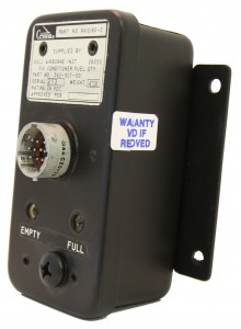
The Capacitive Type Fuel Qty measuring system utilizes a variable capacitive element in order to vary a precise electrical AC voltage based on the quantity of fuel in the fuel tank. The varying electrical signal, in turn, is used to drive the pointer on a fuel quantity indicator in a manner which is proportional to the amount of fuel in the tank, thereby visibly indicating remaining fuel quantity to the pilot.

The typical components in this type of system include the following

1. Signal Conditioner or Control Monitor (If not included in the
indicator
2. Tank Unit (Fuel Qty Sender, Fuel Probe)
3. Indicator                                                                                                          fule flow


Stay tuned for upcoming Blogs

Typical Failures in Resistive Fuel Quantity Systems

Typical Failures in Resistive Fuel Quantity Systems


Indicator

As previously stated the indicator in this type of system is quite simple, typically nothing more than a meter movement mounted within a case. A meter movement consists of a spool of wire mounted on a pivot and jewel housed within a frame. The frame is in fact a large powerful magnet.

As electrical current flows through the wire spool it interacts with the magnetic field of the frame causing the spool to rotate on its pivot and jewel.


Pivots

A pivot is nothing more than a miniature axle. A jewel is a finely ground glass cup within which the ends of the pivot are supported and allowed to rotate. Over time and with constant movement the ends of the pivot will begin to wear down similar to the point on a pencil. Eventually the pivot will become so worn that it can no longer rotate easily. It needs to be sharpened or replaced.


Jewels

As previously stated, a jewel is nothing more than a finely ground miniature glass cup. Glass is fragile; it breaks very easily when mishandled.  The glass also becomes worn from the pivot constantly rotating within it. Eventually the glass will become rough and will need to be re-ground or replaced.


Magnets

The frame of the meter movement is a large magnet. A magnet is nothing more than a piece of steel within which all of the electrons, sub-atomic particles, have been aligned within a specific pattern. Eventually the electrons move and return to their original locations according to the laws of physics. With the loss of alignment the magnet loses its magnetic power.

However while the magnet is still operating properly it, like all magnets, attracts other ferrous metals. The pivot, manufactured with ferrous metal, is in close proximity to the magnet and it is wearing down from rotating within the jewel. As the pivot wears it throws off tiny particles of metal which are attracted to the magnet. Eventually enough of these particles will become lodged between the magnet and wire spool so as to inhibit free movement of the meter. The unit needs to be completely disassembled and thoroughly cleaned.


TANK UNITS


Resistive Elements

As previously described the resistive element is subject to wear from the constant movement of the wiper across its surface. Once it is overly worn or broken it must be replaced. There is no possibility of repair


Floats

The floats are very often nothing more than hollow metal balls. These sometimes spring leaks. The fuel must be drained and the float must be resealed.


Stay tuned for upcoming Blogs

Advantages & Disadvantages of Resistive Type Fuel Systems

Advantages & Disadvantages of Resistive Type Fuel Systems


Advantages of Resistive Type Fuel Measurement Systems

The primary advantage of this type of system is cost. The components are very simple and therefore very inexpensive to manufacture.  A second advantage is reliability. Again these are very simple components involving very few piece parts to manufacture; the fewer parts that are involved then the less that can go wrong. The third and final advantage is that the system, while not optimal, does provide a reasonable amount of accuracy. When utilized on a small aircraft, carrying small quantities of fuel with a limited flight range the accuracy that is provided by this system is adequate.


Disadvantages of Resistive Type Fuel Quantity Systems

Inaccuracy due to Physics
The fuel, within the aircraft’s tanks, is subject to the laws of physics. Therefore it moves when the aircraft moves. It is affected by gravity and centrifugal force. When the aircraft banks for a turn the fuel slops to one side. When the aircraft climbs the fuel flows to the back of the tank. When the aircraft dives the fuel flows towards the front of the tank. The float is in a fixed position and can only respond to the up and down motion of the fuel. If all of the fuel has moved forward and away from the float then the float will fall down and indicate a lower amount of fuel then is currently available, conversely if the mass of fuel gathers in the area where the float is located then the float indicates a higher amount of fuel then what is actually available. Only when the aircraft is flying straight and level will the system provide an accurate report of fuel quantity. These types of inaccuracies are intolerable on a long range aircraft which is carrying thousands of pounds of fuel.


Stay tuned for upcoming Blogs


Theory of Operation (Resistive FQM Systems)

Theory of Operation (Resistive FQM Systems)


For the purposes of discussing the operation of the Resistive Fuel Quantity Measurement System, in the paragraph below, the following assumptions are to be made:


1.   The aircraft utilizes a 28 Volt DC Power Supply

2.   The meter movement within the indicator is the most common type used,      which is a 100mv, d’arsonval type. This means that it requires 100mv of  electrical current to drive the pointer on the meter movement from zero  deflection to full deflection.

When power (V+) is applied to one side the resistive element and ground is applied to the other end and the desired maximum electrical current is 100mv, then Ohm’s Law can be applied in order to determine the required value for the resistive element as follows:

R = E/I

Where R= Resistance, E= Voltage and I = Current.

Since the values of E and I are known, 28 Volts DC and 100mv respectively, then R is resolved as follows:

28/.1 = 280

Therefore the value of the resistive element to be used is equal to 280 Ohms at its minimum value, which would equate to a maximum current flow of 100mv.

A reasonable design, would dictate that the system would change 1mv for each 1% of fuel used. Using that model then 1mv (1% of the fuel remains) would be our zero point on our indicator. Once again Ohm’s Law dictates the value of our resistive element as follows:

28/.01 = 2800 Ohms

Therefore our resistive element must be variable from 280 ohms up to 2,800 Ohms.

The operation of the system is now very straight forward, when the fuel tank is empty the float is at its very lowest point and the wiper resistive element follows the float. Therefore the wiper is at the point of the resistor which is closest to ground and furthest from the source of power or 2800 Ohms. This would provide only 1mv of power to the meter movement and only 1% deflection of the pointer or our Zero (EMPTY) setting.

When the fuel tank is full the float and wiper both will be at their highest point, closest to the source of power or 280 Ohms. This would provide 100mv of power to our meter movement and 100% deflection of the pointer or our FULL setting.

As the voltage is constant and both electrical current and resistance are perfectly linear then our pointer travel will also be perfectly linear.


Stay tuned for upcoming Blogs


Get to Know the Fuel Quantity Indicator

Get to Know the Fuel Quantity Indicator


The indicator for a resistive fuel quantity system is typically a very simple instrument consisting mainly of a meter movement housed within a standard 3-1/8” case. On occasion the indicator may have some signal conditioning element within it, however that is quite rare and when it does occur even that will be a very simple voltage divider or a single stage amplifier.

The most common meter movement used in these indicators is of the d’arsonval type and which is typically 100 milli-volts full scale.


Stay tuned for upcoming Blogs

Fuel Measuring Systems- Tank Unit

Fuel Measuring Systems- Tank Unit


The tank unit is the component which gives the system its name “Resistive Fuel Quantity Measuring System”. The tank unit is comprised of a float which is mechanically linked to a variable resistive element. The float rides on top of the fuel and will move up or down depending on the level of fuel within the tank. The floats movement is coupled via a linkage arm and gear assembly to a variable resistive element which then mimics the movement of the float.

The variable resistive element is comprised of two parts; a resistive strip, typically manufactured with Nichrome wire, and a wiper assembly. Nichrome wire has a predictable and stable resistance to electricity per inch of wire. Therefore it is possible to cut and form a piece of nichrome wire to a very exact electrical resistance value simply by adjusting the length of wire.

The wiper assembly is a moveable electrical contact which slides across the length of the nichrome wire while making direct physical contact with the wire. In our fuel measuring system one end of the nichrome wire will be connected to the aircraft power source and the other end will be connected to ground. The wiper will tap a varying amount of electricity off of the nichrome due to its physical contact. The amount of electricity that is tapped is determined by the overall resistive value of the wire and precisely where on the wire that the wiper is making physical contact. If the wiper has moved 24% down the length of the wire then 75% of the electricity is tapped off; at 50% movement then 50% is tapped off; at 75% movement then 25% is tapped off. This relationship is very predictable and very consistent and operates precisely under the principles of Ohm’s Law (E=I/R).

The electricity that is tapped off by the wiper is then transmitted by wire directly to the Fuel Quantity Indicator and is used to drive the pointer indicating fuel qty.


Stay tuned for upcoming Blogs

Fuel Measuring Systems- Regulated Power Source

Fuel Measuring Systems-Regulated Power Source


In most resistive type fuel qty. systems the aircrafts own power source (14 VDC or 28VDC) is used as the power for the quantity system. While the aircraft power is reasonably well regulated it is not a precise regulation, hence the first negative for resistive systems. Aircraft power can vary from approximately 12.6 volts up to 17 volts on a nominally 14 volt aircraft. On a 28 volt aircraft the power supply can vary from 24 volts up to 31 volts. The aforementioned variances are under normal operating conditions, if the power supply is experiencing technical problems then the variance can be significantly more.


Stay tuned for upcoming Blogs

Photo Lineup